


Price:





European delivery - 30 working days, other countries +7 working days.
Ask a question about this item
Ask a question about this item
ICA ATEX GAS and H₂ – explosion-proof corrosion-resistant centrifugal fans for corrosive gas and hydrogen atmospheres ≤7100 m³/h
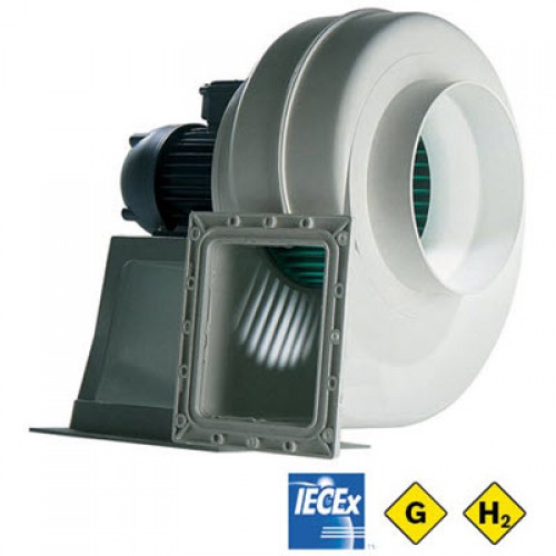
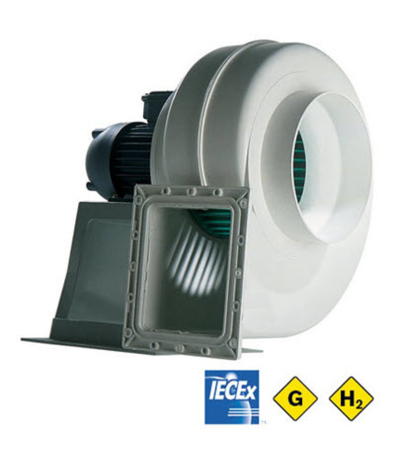
DYNAIR / MAICO ITALIA ICA ATEX industrial centrifugal fans are manufactured with antistatic polypropylene casings and impellers for conveying corrosive, non-abrasive fumes and vapours in potentially explosive gas atmospheres. The fans are classified as ATEX equipment category II 3G for Zone 2 and the series delivers airflow up to 7100 m³/h. The manufacturer also includes ICA in its gas and hydrogen ATEX range; however, suitability for hydrogen must be documented for the specific complete fan assembly with an IIB+H2 or IIC classification.
Standard ICA ATEX equipment is classified as II 3G for Zone 2, with minimum catalogue motor classification EEx d IIB T3. Hydrogen belongs to gas group IIC. Operation in hydrogen atmospheres requires documentation establishing suitability of the specific fan assembly and its electrical equipment for IIC or the hydrogen-specific IIB+H2 classification. Standard IIB classification alone does not establish suitability for hydrogen.
Standard discharge orientation LG0°. Eight positions are available: LG0°, LG45°, LG90°, LG135°, LG180°, LG225°, LG270° and LG315°.

Accessories are not included in the Type Examination Certificate. Their suitability for the specific ATEX installation must be assessed separately.
ICA ATEX – technical catalogue (PDF)
All dimensions are in millimetres (mm); indicative weights are in kilograms (kg). Dimension symbols correspond to the manufacturer's drawing.
| Model | B | ØC | D | E | F | G | H | Y | K | I | L | M | N | O | Øb |
|---|---|---|---|---|---|---|---|---|---|---|---|---|---|---|---|
| ICA ATEX 120 | 90 | 125 | 103 | 105 | 135 | 265 | 130 | 63 | 28 | 172 | 175 | 288 | 130 | 55 | 10 |
| ICA ATEX 160 | 135 | 200 | 148 | 148 | 201 | 397 | 200 | 80 | 52 | 248 | 215 | 435 | 130 | 55 | 10 |
| ICA ATEX 200 | 165 | 250 | 185 | 180 | 250 | 495 | 250 | 80 | 45 | 250 | 255 | 460 | 175 | 128 | 10 |
| ICA ATEX 250 | 202 | 315 | 222 | 214 | 299 | 590 | 310 | 90 | 84 | 282 | 234 | 568 | 175 | 155 | 12 |
| ICA ATEX 350 | 237 | 355 | 259 | 275 | 349 | 690 | 320 | 100 | 91 | 370 | 285 | 698 | 200 | 173 | 12 |
| Model | P | Q | R | S | T | U | V | Øa | Holes | kg |
|---|---|---|---|---|---|---|---|---|---|---|
| ICA ATEX 120 | 135 | 135 | 110 | 110 | 85 | 85 | 110 | 7.5 | 4 | 13 |
| ICA ATEX 160 | 180 | 210 | 164 | 194 | 130 | 160 | 85 | 7 | 6+2 | 15/27 |
| ICA ATEX 200 | 228 | 266 | 202 | 240 | 160 | 200 | 80 | 7 | 8+2 | 57 |
| ICA ATEX 250 | 265 | 306 | 241 | 282 | 195 | 240 | 100 | 9 | 6+4 | 45 |
| ICA ATEX 350 | 305 | 356 | 275 | 326 | 225 | 280 | 100 | 9 | 8+4 | 70 |
ICA ATEX – original dimensional drawing (PDF, page 3)
| Code | Fan size | ØA, mm | B, mm |
|---|---|---|---|
| 5RD1015 | 120 | 125 | 95 |
| 5RD1021 | 160 | 200 | 168 |
| 5RD1025 | 200 | 250 | 160 |
| 5RD1027 | 250 | 315 | 170 |
| 5RD1026 | 350 | 315 | 210 |
| 5RD1028 | 350 | 355 | 210 |
| Parameter | Value |
|---|---|
| Manufacturer | DYNAIR / MAICO ITALIA, Italy |
| Series | ICA ATEX |
| Type | Corrosion-resistant centrifugal fan |
| Operating environment | Corrosive, non-abrasive gas and vapour atmospheres, ATEX Zone 2 |
| ATEX equipment category | II 3G |
| Minimum catalogue motor classification | EEx d IIB T3 |
| Hydrogen applications | Subject to IIC or IIB+H2 conformity documentation for the specific fan assembly |
| Maximum series airflow | 7100 m³/h |
| Operating temperature | -20 °C to +40 °C |
| Power supply | 400 V / 3-phase / 50 Hz |
| Motor power | 0.12–3.00 kW |
| Motor protection class | IP55 |
| Insulation class | F |
| Duty rating | S1 |
| Motor mounting arrangement | B3 or B5 |
| Speed control | Not provided |
| Casing | Antistatic polypropylene |
| Impeller | Polypropylene, forward-curved blades |
| Standard discharge orientation | LG0° |
| Available orientations | 8, in 45° increments |
| ATEX Directive | 2014/34/EU |
| Fan safety standard | EN 14986:2017 |
| Antistatic material requirements | EN IEC 60079-0, clause 26.13 |
| Code | Model | Poles | Power, kW | Current, A | IP / class | IE3 | Lp, dB(A) |
|---|---|---|---|---|---|---|---|
| 7IA1205 | ICA ATEX 120 | 2 | 0.12 | 0.56 | 55/F | – | 68 |
| 7IA1611 | ICA ATEX 160/4 | 4 | 0.18 | 0.84 | 55/F | – | 57 |
| 7IA1612 | ICA ATEX 160/2 | 2 | 1.10 | 2.60 | 55/F | Yes | 70 |
| 7IA2007 | ICA ATEX 200 | 4 | 0.55 | 1.70 | 55/F | – | 66 |
| 7IA2507 | ICA ATEX 250 | 4 | 1.10 | 3.00 | 55/F | Yes | 65 |
| 7IA3504 | ICA ATEX 350 | 4 | 3.00 | 7.10 | 55/F | Yes | 70 |
Lp is the sound pressure level under free-field conditions at the point of maximum efficiency, measured at a distance of 1.5 m according to EN ISO 13349 measurement category D.
Air performance is determined according to EN ISO 5801 / AMCA 210 at an air density of 1.2 kg/m³.
Actual airflow and static pressure of each model are selected using the manufacturer's aerodynamic performance curves.
ICA ATEX – technical specifications and performance curves (PDF)
ICA ATEX fans are intended to convey corrosive, non-abrasive fumes and vapours in industrial ventilation systems where potentially explosive gas atmospheres may occur. Before installation, verify that the specific fan's ATEX equipment category II 3G and its documentation are appropriate for the Zone 2 installation conditions.
The standard discharge orientation is LG0°. Eight positions are available, from LG0° to LG315°, in 45° increments.
Regularly inspect the casing, impeller, motor, fasteners and electrical connections. Remove deposits and check for chemical damage to the polypropylene components. Before maintenance, disconnect the power supply, prevent accidental restarting and observe the safety procedures applicable to potentially explosive atmospheres.
You might also like: