


Price:





European delivery - 30 working days, other countries +7 working days.
Ask a question about this item
Ask a question about this item
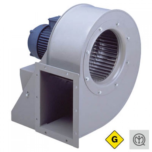
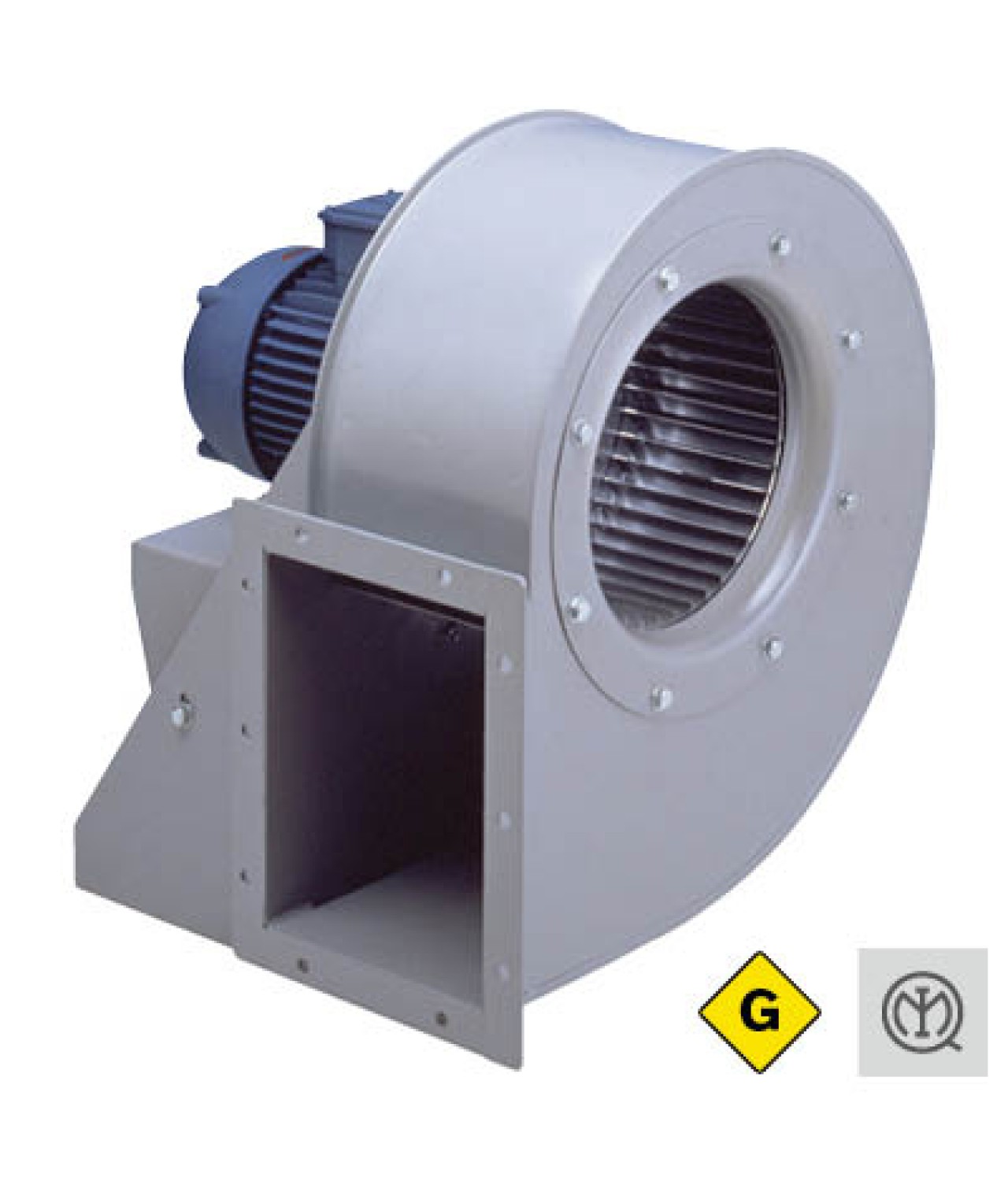
AL ATEX GAS – ATEX explosion-proof centrifugal fans with forward-curved impeller, up to 10,770 m³/h
AL ATEX GAS centrifugal fans with forward-curved Sirocco-type impellers are designed for transporting clean air containing potentially flammable gases, vapours or mists in explosive atmospheres. Suitable for Zone 1, they comply with ATEX Directive 2014/34/EU. The highest maximum airflow of the catalogue-listed models is 10,770 m³/h.
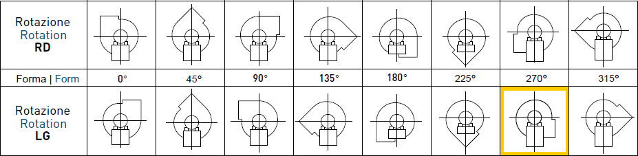
Standard casing position: LG270°. LG and RD discharge orientations are available in 45° increments. The 180° and 225° positions require special construction and must be specified when ordering.
Accessories are not included in the fan type-examination certificate. Their suitability for the specific ATEX installation must be confirmed with the manufacturer.
AL ATEX GAS – technical catalogue (PDF)
Dimensions are in millimetres (mm); weights are in kilograms (kg). Dimension references are illustrated in the drawing below. The tables contain AL ATEX GAS data.
| Size | A | B | C | D | E | F | G | H | I | L | ØM | kg |
| AL ATX 200 | 183 | 176 | 120 | 156 | 280 | 70 | 355 | 103 | 140 | 218 | 12 | 20 |
| AL ATX 225 | 210 | 193 | 141 | 175 | 310 | 78 | 345 | 111 | 140 | 218 | 12 | 32 |
| AL ATX 250 | 231 | 210 | 162 | 193 | 335 | 90 | 375 | 120 | 205 | 270 | 12 | 39 |
| AL ATX 280 | 257 | 230 | 170 | 216 | 365 | 98 | 410 | 132 | 205 | 270 | 12 | 40 |
| AL ATX 315 | 288 | 252 | 192 | 245 | 405 | 109 | 570 | 140 | 205 | 319 | 12 | 55 |
| AL ATX 355 | 321 | 275 | 212 | 270 | 445 | 121 | 480 | 153 | 245 | 354 | 15 | 73 |
| AL ATX 400 | 358 | 303 | 235 | 301 | 505 | 136 | 650 | 168 | 245 | 370 | 15 | 123 |
| AL ATX 450 | 406 | 337 | 267 | 337 | 560 | 151 | 695 | 183 | 340 | 439 | 15 | 146 |
| Size | a | b | c | d | e | f | g | h | Øi | Øl | Øm | Øn | n°o |
| AL ATX 200 | 180 | 135 | 75 | 213 | 100 | 168 | 240 | 195 | 164 | 235 | 255 | M6 | 10 |
| AL ATX 225 | 200 | 155 | 75 | 233 | 100 | 188 | 260 | 215 | 189 | 260 | 280 | M6 | 10 |
| AL ATX 250 | 220 | 175 | 75 | 253 | 100 | 208 | 280 | 235 | 210 | 290 | 310 | M6 | 10 |
| AL ATX 280 | 260 | 195 | 100 | 293 | 125 | 228 | 320 | 255 | 240 | 310 | 340 | M8 | 10 |
| AL ATX 315 | 300 | 215 | 100 | 333 | 150 | 248 | 360 | 275 | 275 | 335 | 375 | M8 | 10 |
| AL ATX 355 | 340 | 240 | 125 | 373 | 100 | 273 | 400 | 300 | 302 | 395 | 425 | M8 | 12 |
| AL ATX 400 | 388 | 273 | 125 | 425 | 100 | 310 | 465 | 350 | 352 | 445 | 465 | M8 | 12 |
| AL ATX 450 | 430 | 300 | 150 | 470 | 100 | 340 | 510 | 380 | 402 | 490 | 520 | M8 | 12 |
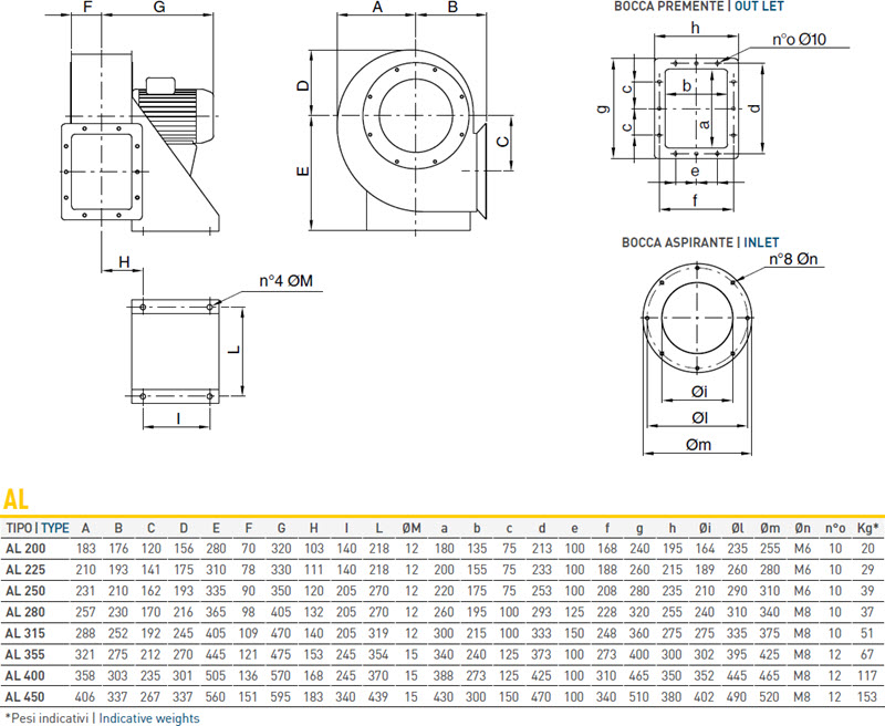
The drawing illustrates the standard AL series. For AL ATEX GAS, use the dimensions and weights in the tables above, which may differ from the standard AL series.
| Parameter | Value |
| Fan type | Forward-curved centrifugal fan |
| Highest catalogue-listed maximum airflow | 10,770 m³/h |
| Motor power | 0.25–9.00 kW |
| Fan sizes | 200–450 |
| ATEX marking | II 2G Ex h IIB T4 Gb |
| Certificate | IMQ 10 ATEX 017 X |
| Operating temperature | −20 °C to +60 °C |
| Motor protection | IP55 |
| Insulation class | F |
| Duty | S1 |
| Catalogue model supply | 400 V / 3 phases / 50 Hz |
P = number of motor poles; Pm = motor power; In = rated current; Qmax = maximum airflow; Pt min = minimum total pressure indicated by the manufacturer.
| Code | Model | P | Pm, kW | In, A | Qmax, m³/h | Pt min, Pa |
| 1XA2026 | 202 | 2 | 1.10 | 2.40 | 1700 | 1050 |
| 1XA2027 | 204 | 4 | 0.25 | 0.80 | 1550 | 211 |
| 1XA2225 | 222 | 2 | 2.20 | 4.40 | 2720 | 1382 |
| 1XA2226 | 224 | 4 | 0.55 | 1.50 | 1950 | 329 |
| 1XA2539 | 252 | 2 | 3.00 | 5.50 | 2920 | 472 |
| 1XA2540 | 254 | 4 | 0.75 | 2.00 | 2450 | 371 |
| 1XA2541 | 256 | 6 | 0.37 | 1.25 | 1930 | 124 |
| 1XA2839 | 284 A | 4 | 1.50 | 3.30 | 3540 | 452 |
| 1XA2840 | 284 B | 4 | 1.10 | 2.70 | 3540 | 452 |
| 1XA2841 | 286 | 6 | 0.75 | 2.70 | 2820 | 174 |
| 1XA3136 | 314 A | 4 | 3.00 | 6.50 | 5760 | 482 |
| 1XA3137 | 314 B | 4 | 2.20 | 5.50 | 5760 | 482 |
| 1XA3138 | 316 | 6 | 1.10 | 2.70 | 4200 | 195 |
| 1XA3515 | 354 A | 4 | 4.00 | 8.80 | 7660 | 425 |
| 1XA3516 | 354 B | 4 | 3.00 | 6.50 | 6715 | 500 |
| 1XA3517 | 356 | 6 | 1.50 | 3.80 | 5030 | 197 |
| 1XA3518 | 358 | 8 | 0.75 | 2.60 | 3680 | 90 |
| 1XA4022 | 404 A | 4 | 7.50 | 14.40 | 9300 | 250 |
| 1XA4023 | 404 B | 4 | 5.50 | 11.94 | 5850 | 1115 |
| 1XA4024 | 406 | 6 | 2.20 | 5.40 | 6290 | 325 |
| 1XA4025 | 408 | 8 | 1.10 | 3.00 | 4720 | 185 |
| 1XA4507 | 454 | 4 | 9.00 | 17.50 | 10770 | 1200 |
| 1XA4508 | 456 | 6 | 4.00 | 8.64 | 7140 | 355 |
| 1XA4509 | 458 | 8 | 2.20 | 5.20 | 5450 | 200 |
Qmax and Pt min for models 284 A/B and 314 A/B are shown using the combined catalogue entries for their respective size groups. Check the individual performance curve before selecting a specific model.
AL ATEX GAS – technical catalogue and performance curves (PDF)
AL ATEX GAS fans are intended for industrial ducted ventilation systems where explosive atmospheres containing gases, vapours or mists may occur. Before installation, verify that the selected fan's ATEX marking II 2G Ex h IIB T4 Gb is suitable for the hazardous area classification, gas group and temperature requirements.
Fans with forward-curved impellers must always be connected to a duct system. Where necessary, additional aerodynamic resistance, such as a regulating damper, must be provided. Airflow must be limited so that the motor current does not exceed the value stated on the motor rating plate.
The standard casing position is LG270°. Select the discharge orientation according to the duct layout. LG and RD positions are available in 45° increments; 180° and 225° require special construction and must be agreed before ordering.
Electrical installation must be carried out by qualified personnel in accordance with the motor rating plate, manufacturer instructions and electrical requirements applicable to explosive atmospheres.
Connect the PTC thermistors to a compatible protective device. Frequency-inverter speed control of three-phase models is permitted only under the conditions specified by the manufacturer and the motor explosion-protection requirements.
Regularly inspect the impeller, casing, fasteners, motor and protection devices. Perform maintenance only after safely disconnecting the electrical supply and preventing unintended restart.
You might also like: